VAG vehicles on the MLB Evo platform (2016+)
This guide covers vehicles on the MLB Evo platform (Audi A4/A5, A6/A7, A8, Q5, Q7, Q8 and related, 2016+). The exact location of individual components and the connector layout may vary slightly between models – that’s normal; the connection principle is the same.
The module connects in parallel to the Comfort CAN bus via a T-connector and is powered from the fuse box. It only sends CAN packets – it does not physically switch the light circuit and requires no reflashing (coding) of the car.
0. What you need
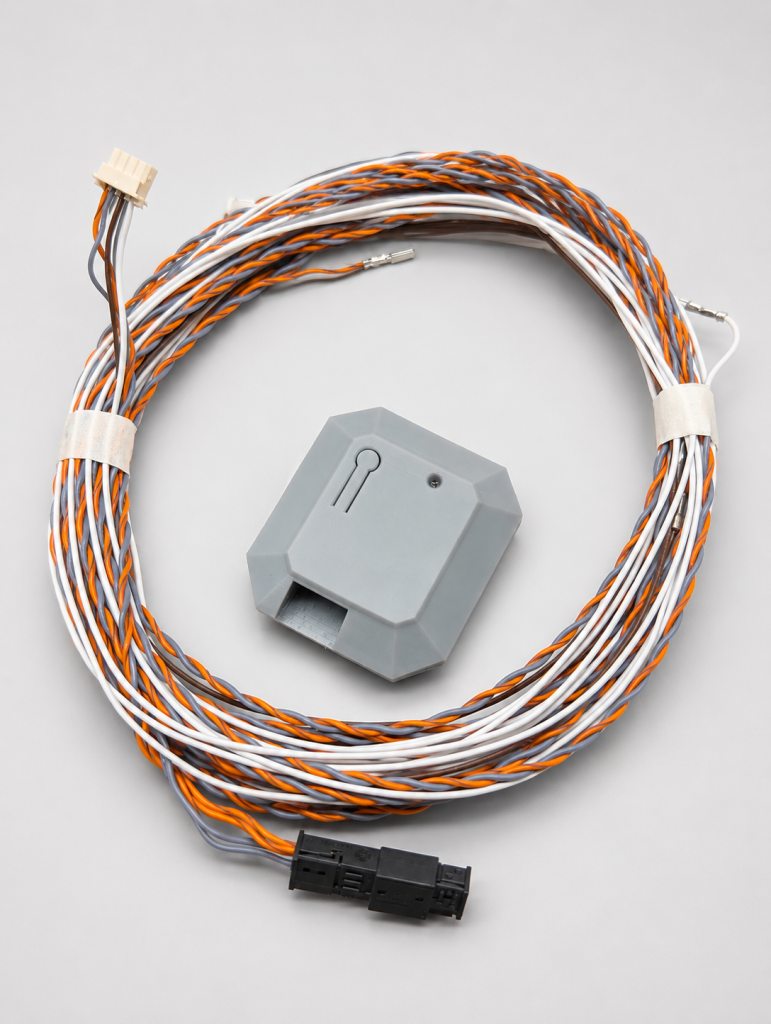
In the box:
- Strobe Module
- Wiring harness with connectors (T-connector + terminals)
- Fuse
- Quick instruction
Additional tools you’ll need:
- Socket/wrench for the battery terminal – usually 10 mm (check the actual nut size on your terminal)
- A thin tool to release the terminal – a sewing needle, a thin flat screwdriver, a straightened paperclip or a pin
- Gloves, a flashlight
⏱️ Estimated time: ~20 min.
1. ⚠️ Safety – read before you start
- Disconnect the battery terminal with the ignition ON but the engine off (do not start the engine).
- Disconnect the negative (-) terminal first, and only then touch any wiring. This de-energizes the vehicle’s electrical system and rules out accidental deployment of safety components.
- Don’t pull connectors by the wires – only by the connector housing, after releasing the latch.
- Only the lower seat cushion is removed – we don’t touch the backrests with the side airbags.
2. Disconnecting the battery (negative terminal)
On most MLB Evo cars the battery is located in the luggage compartment (e.g. on the right, under the floor), not in the engine bay; under the hood there is only a jump-start terminal.
On some models the location may differ – check the owner’s manual if in doubt.
- Switch the ignition on without starting the engine (on cars with a Start button – press Start without pressing the brake pedal). This lets the control units shut down properly.
- Open the trunk, lift the floor (mat) and secure it on the standard hook. Remove the protective panel/cover over the battery if needed.
- Find the black negative (-) terminal.
- Loosen the terminal clamp nut with a wrench (don’t fully unscrew the bolt).
- Lift the terminal off the battery post with an upward motion and move it aside so it can’t touch the post.
- Wait 2-5 minutes before working with the wiring. Take a sip from your glass or a few thoughtful drags – savor the moment of a DIY upgrade.
3. Removing the rear seat cushion
On sedans (A4, A6, A8) you remove the lower cushion of the one-piece bench. On crossovers (Q5, Q7, Q8) the seat construction and mounts may differ – adapt the steps to your model. The principle (release the clips and lift the cushion) is the same.
Only the lower cushion (the one you sit on) is removed.
- Slide the front seats all the way forward – this gives you room to pull the cushion.
- Remove the plastic covers/guides of the ISOFIX (child-seat) anchors at the junction of the cushion and backrest – everything comes off by hand (pry the cover off with your fingers, push the guide down and pull it forward).
- The cushion is held by two clips (one on each side) at the front, roughly centered behind each front seat.
- Slide your fingers between the front edge of the cushion and the carpet and pull the cushion up sharply – first on one side, then the other, applying even force. The cushion’s wire hooks will pop out of their mounting sockets. Some force is required – that’s normal. The Germans built it to last, so pull with confidence: the cushion is tougher than your doubts. Evenly on both sides, and without overdoing it.
- Before fully removing it, check the underside of the cushion – if there’s a cable/wire there, disconnect it.
- Take the cushion out of the cabin and set it aside.
4. Accessing the J533 diagnostic module (Gateway)
On MLB Evo cars the J533 module (gateway) is usually hidden under the rear seat (in the center) – classic German logic: put the most important node of the vehicle network exactly where it’s hardest to reach.
On some models the exact spot may differ.
- Find the black J533 module under where the cushion used to be.
- Remove the sound insulation/cable ties covering access to the module’s connectors (remember how they were positioned – you’ll put them back).
- Inspect the connectors going into the module.
5. Identifying the right connector and pins
This is the end point of “finding the pins on the connector.”
On later cars (approx. MY2018+) the J533 module has two 54-pin connectors. On earlier ones – the connector layout may differ; go by the printed numbering.
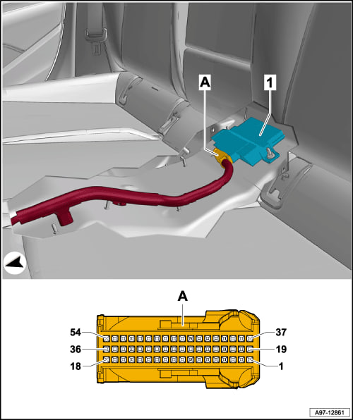
The Comfort CAN bus, which the module connects to:
| Signal | Pin |
|---|---|
| CAN-High | 15 |
| CAN-Low | 33 |
How to find these pins physically:
- The connector housing has fine pin numbering printed on it (digits next to the rows of pins). Use it to locate positions 15 and 33.
- Cross-check with the vehicle wiring diagram (ELSA/ODIS).
⚠️ Before extraction, confirm the physical location of pins 15 and 33 (which connector and row exactly) against the printed numbering and the diagram. The wrong pin can disrupt the bus.
6. Connecting via the T-connector
Principle: the factory terminal is pulled out of the module’s connector, our terminal goes in its place, and the factory terminal is then routed onward through the T-connector of our harness. This puts the module in parallel on the CAN-H and CAN-L lines.
For each of the two terminals (15 → CAN-H, 33 → CAN-L):
- Release the connector lock (secondary lock / CPA) that holds the terminals – usually a colored slider bar.
- With a thin tool (needle / thin screwdriver / straightened paperclip) press the small terminal locking tab inside the cavity and carefully pull the factory terminal out of the connector housing, gently tugging the wire.
- Insert our terminal (from the module’s harness) into the freed cavity until it clicks/locks.
- Insert the factory terminal you just pulled out into the matching cavity of our harness’s T-connector – until it locks.
- Put the connector lock back in place.
- Repeat for the second signal.
Check that all terminals are fully seated and locked, and that the polarity isn’t swapped (H to H, L to L).
7. Connecting power
The module’s harness has a terminal for a mini fuse that goes into a spare slot in the fuse box, plus the fuse from the kit.
- Find a spare mini-fuse slot in the fuse box (on the B9 there’s a convenient fuse box on the left of the luggage compartment; on other models the box location may differ).
- Insert the harness’s fuse-tap terminal into that slot.
- Install the fuse from the kit.
- Make sure the tap sits firmly and the contact is secure.
8. Reassembly and check
- Connect the harness to the connector on the module – push it in until it locks and give it a gentle tug to check. Then neatly secure the harness so it can’t rattle or chafe. Do it tidily – so you won’t be embarrassed to show it to the next owner someday: a clean install is part of the upgrade too. Position the module so it doesn’t press on the connectors or get in the way of the cushion.
- Put the sound insulation/seal of the J533 module back in place.
- Reinstall the lower seat cushion: guide the wire hooks into the sockets and press down until it clicks on both sides. Put the ISOFIX covers/guides back.
- Return the front seats to a comfortable position.
- Reconnect the battery negative (-) terminal last, tighten the clamp nut. Put the panel/cover over the battery and the trunk floor back.
- Make sure the connector is fully seated.
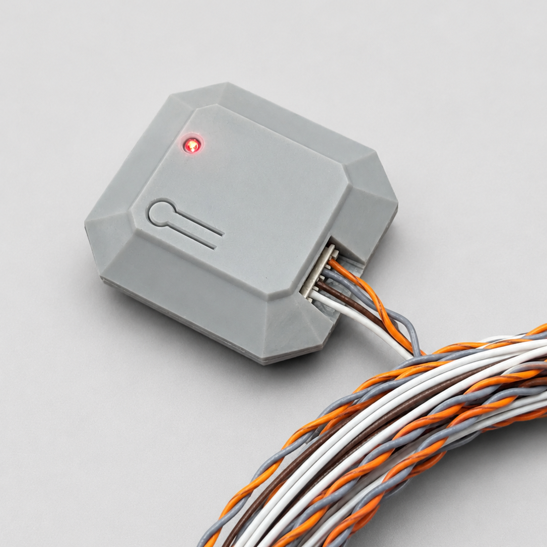
Check:
- Turn on the ignition. Make sure there are no new warnings (Airbag, network errors).
- Test the strobe on the high beam as intended. If it flashes the way it should – congratulations: you’ve just done by hand something you won’t find on any dealer’s price list.
9. After installation
- After disconnecting the terminal, some functions may need re-initialization (e.g. one-touch auto windows): raise the window fully and hold the button up for 1-2 s, then lower it fully and hold it down – for each window.
- The clock/some personal settings may reset – set them as needed.
10. Usage
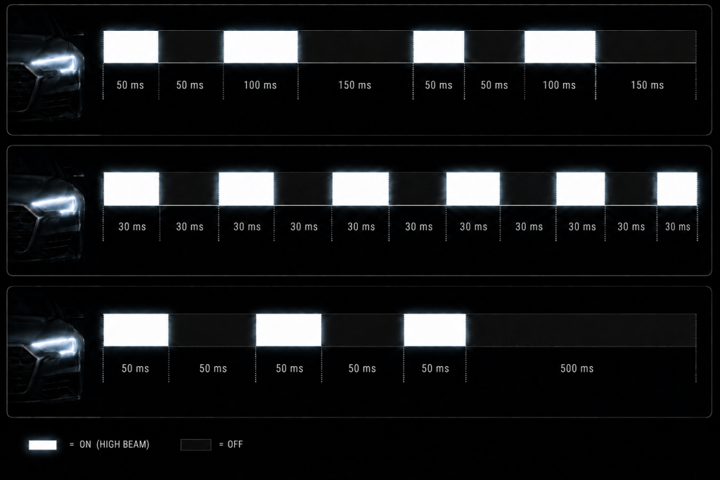
The current version of the device has 3 flash modes, switched by a single press of the button on the module: